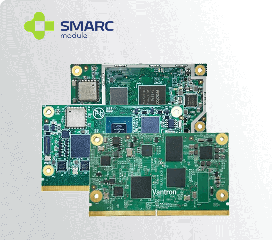
Selecting an i.MX8 module is often the easy part of an embedded design. The harder work, and the part most likely to introduce delays, happens on the carrier board that surrounds it. A well-planned carrier board can turn a capable processor module into a reliable finished product; a poorly planned one can undo every advantage the module was meant to provide.
Understanding the Division of Labor Between Module and Carrier Board
An i.MX8 SoM handles the processor, memory, and core logic, but it depends on the carrier board to expose that capability to the outside world. Power regulation, connector placement, display routing, and peripheral wiring all live on the carrier side, which means design decisions here directly determine how the finished product behaves.
Treating the carrier board as an afterthought can create integration problems. Although a SoM reduces the complexity of the core processor subsystem, the carrier board and completed product still require careful power, interface, signal-integrity, thermal, mechanical, and compliance design.
Power Input Design for an i.MX8 SoM Carrier Board
Power architecture is one of the first decisions a carrier board design must resolve. Many i.MX8-based modules expect a specific input voltage, and Vantron’s own SMARC carrier board reference design, for example, is built around a +12V DC input, which needs to be reflected accurately in any custom power supply design built around it.
Sequencing matters just as much as voltage level. Processor modules typically require power rails to come up in a defined order, and getting this wrong can prevent the module from booting reliably or cause intermittent failures that are difficult to diagnose later. Reviewing the module’s datasheet power sequencing requirements early avoids this problem entirely.
Planning Display and Camera Interfaces Early
Display connectivity is another area where carrier board decisions carry weight. SoMe interfaces exposed by an i.MX8 SoM, such as eDP on certain SMARC designs, are not directly wired to the processor and require careful verification before a display connector is committed to the layout, since assuming universal support can lead to a non-functional design.
Camera interfaces deserve similar attention. Vantron’s SMARC carrier board supports two MIPI CSI camera interfaces, which is a common requirement for machine vision and inspection applications. Confirming lane configuration and connector pinout against the specific module variant in use prevents a costly respin after prototypes are already built.
Connector and Form Factor Considerations Across Module Types
Not every i.MX8 module shares the same form factor, and this affects carrier board compatibility directly. A System on Module built on the SMARC standard uses a different edge connector and pin arrangement than one built on Q7, so a carrier board designed for one standard cannot simply accept the other without modification.
This distinction matters when planning for future scalability. Choosing a consistent form factor across a product family, rather than mixing standards between variants, allows a single carrier board design to support multiple processing tiers over time, reducing the engineering effort required for each new product revision.
Software and Driver Alignment During Carrier Board Bring-Up
Hardware design is only half the carrier board equation. Once the board is populated, drivers and board support packages need to align with the specific peripherals wired into the design, including display timing configurations, camera sensor drivers, and any custom interface routing that differs from the reference layout.
Bring-up delays often trace back to mismatches between what the hardware team assumed and what the software team implemented. Close coordination between hardware and firmware engineers during the design phase, rather than after boards arrive from fabrication, significantly reduces the debugging time required to reach a stable, working prototype.
How Vantron Supports Carrier Board Design for System on Module Deployments
Vantron addresses these challenges directly by pairing its System-on-Module lineup with matching carrier board reference designs and documentation, including detailed user manuals covering power input requirements, display interface behavior, and camera connectivity. This gives engineering teams a validated starting point rather than a blank layout built purely from a processor datasheet.
For modules such as the VT-SBC-SMARC-8MP, built around the NXP i.MX8M Plus processor, and the VT-SBC-IMX8XQ7, based on the i.MX 8QuadXPlus, Vantron provides corresponding carrier board datasheets that outline exactly how each interface is routed. This lets integrators verify assumptions before committing to a custom board rather than discovering mismatches after prototypes are built.
Vantron’s engineering support extends beyond documentation, with FAE assistance available to help teams work through power sequencing questions, interface conflicts, and driver alignment issues as they arise. For manufacturers building around an i.MX8 SoM, this combination of validated reference designs and direct technical support often determines whether a carrier board reaches a stable prototype on the first attempt or requires multiple costly revisions.
Carrier board design will never be reduced to a simple checklist, since every product brings its own mix of interfaces, environmental requirements, and software dependencies. What a solid reference design and responsive engineering support can do is remove the avoidable risks, letting teams spend their effort on genuine product differentiation instead of relearning lessons that a validated System on Module platform had already solved.
